


AC Motor Types and Their Industrial Uses
Views: 0 Author: Site Editor Publish Time: 2026-09-23 Origin: Site


An alternating current motor turns electrical energy into mechanical rotation. These machines run pumps, conveyors, compressors, and many other industrial loads every day. Engineers often ask what ac motor types exist and which jobs each one does best. Two families lead the field: synchronous motors and induction motors. Each family splits into several designs, and each design fits specific tasks. This guide helps engineers and plant managers choose the right machine. It explains how a synchronous unit holds steady speed and corrects power factor. It also shows why an induction unit works as the industrial workhorse. Readers will learn why use an ac motor over other options and how to match torque, speed, and duty cycle to real equipment.
Key Takeaways
Synchronous motors keep exact speed and correct power factor for heavy industrial loads.
Induction motors are the industrial workhorse, with low cost and easy upkeep.
Squirrel cage motors are the most common choice for everyday jobs like pumps, fans, and conveyors.
Wound rotor motors give strong starting power for cranes, hoists, and mills.
Variable-frequency drives can lower energy use by 20 to 30 percent for pumps and fans.
AC Motor Types and How They Work
Stator, Rotor, and Rotating Magnetic Field
An alternating current motor depends on two main parts: a stator that stays still and a rotor that spins. The stator holds coils that carry alternating current. When a balanced three-phase supply feeds the stator winding, the three phase windings sit 120 electrical degrees apart in space. Their currents also shift 120 degrees in time. Each phase makes a pulsing flux along its own axis. Together, they create a magnetic field of steady strength that rotates around the stator. This combined flux equals 1.5 times the top flux of one phase. It spins at synchronous speed, found by Ns = 120f/P, where f is frequency in hertz and P is the number of poles. The rotor then chases this field to make torque. The direction of spin depends on the phase sequence of the supply.
Three-Phase vs. Single-Phase Power
Three-phase ac motors rule larger industrial jobs. They shine above 1–2 HP and go up to hundreds or thousands of HP. For the same horsepower, a three-phase motor is smaller, lighter, and stronger. It also gives high starting torque of 200–300% or more, with smooth pickup and better speed control. Common uses include large pumps, compressors, conveyors, elevators, HVAC chillers, and machine tools. Single-phase ac motors handle lighter loads. They cover fractional HP up to about 5–10 HP. Bigger sizes get bulky, wasteful, and pricey. Their starting torque is lower, often 100–200% of full-load torque. They fit fans, blowers, small pumps under 2–3 HP, and bench grinders. Engineers who ask why use an ac motor often find that three-phase induction motors give the best efficiency for steady heavy work. A variable-frequency drive (VFD) further adjusts speed and torque by controlling applied frequency and voltage. During starting, a VFD applies low frequency and voltage, then ramps them up. This avoids high inrush current and can let the motor build about 150% of rated torque while pulling less than 50% of rated current from the mains at low speed.
Synchronous AC Motor: Constant Speed and Power Factor
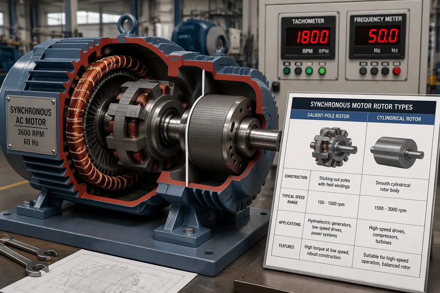
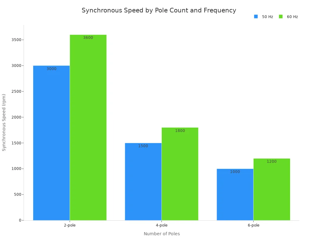
Engineers compare ac motor types by speed control, starting torque, and maintenance. The synchronous ac motor is different because its rotor locks onto the stator's rotating magnetic field. On a 60 Hz supply, a two-pole machine spins at 3,600 rpm, a four-pole machine at 1,800 rpm, and a six-pole machine at 1,200 rpm. On a 50 Hz supply, the same pole counts give 3,000 rpm, 1,500 rpm, and 1,000 rpm. The rotor never falls behind. This "no slip" behavior sets it apart from the induction motor, which always runs a little behind the rotating field.
Construction and Operating Principle
A synchronous motor uses a stationary armature and a rotating field winding. The stator makes a magnetic field of steady strength and turns it around the air gap. The rotor carries a direct-current winding, which turns it into a fixed electromagnet. Once the rotor gets close to synchronous speed, the stator field pulls it into step. The rotor then spins at exactly the same speed as the field.
The rotor's physical construction follows the pole count. A cylindrical round rotor, or non-salient pole rotor, fits machines with up to six poles. A salient-pole rotor uses sticking-out laminated-steel poles and fits machines with many poles. Salient-pole rotors turn at low speed, about 100 to 1,500 rpm. Cylindrical rotors turn at high speed, about 1,500 to 3,000 rpm. Salient designs often include damper windings to reduce rotor shaking. Cylindrical designs do not need them. The table below compares both rotor forms.
Feature | Salient Pole Rotor | Cylindrical Rotor |
|---|---|---|
Speed range | Low speed, about 100–1,500 rpm | High speed, about 1,500–3,000 rpm |
Pole count | Usually 4–60 poles | Usually 2–4 poles |
Flux waveform | Poorer flux distribution | Sinusoidal, cleaner waveform |
Typical use | Hydroelectric plants, slow turbines | Nuclear, gas, and thermal power plants |
Synchronous speed also depends on line frequency. The chart below compares pole counts at 50 Hz and 60 Hz.
The direct field current controls more than speed. It also controls power factor. A low field current gives a lagging power factor. A high field current gives a leading power factor. An engineer can set a synchronous motor to lead, and that leading current cancels out the lagging reactive demand from induction motors. This action lowers reactive power demand and cuts utility penalties. Modern plants rarely install a synchronous unit only for correction, though, because its application range is narrow compared with induction motors.
Industrial Applications and Limitations
Synchronous motors handle heavy loads that need constant speed or managed reactive power. Typical industrial uses include:
Large compressors and pumps that need steady speed
Ball mills, crushers, and rolling mills in mining and metals processing
Over-excited motors that make up for lagging power factor from induction motor loads
Mine hoists and marine propulsion driven through variable-speed converters
In fixed-speed service, the stator connects to the grid at rated frequency. The motor then runs at one mechanical speed. In variable-speed service, a converter changes stator frequency and voltage. The excitation system and converter must be designed together for the required speed range, torque, and transient behavior.
The design still carries important limits. A synchronous motor needs an outside starting source, while an induction motor starts directly from the stator supply. The synchronous rotor also needs a DC supply, so the machine is doubly excited. It cannot use slip to raise torque under overload. These types of ac motors therefore cost more and need more complex control. Their best place is large, constant-speed industrial processes where power factor matters more than flexibility.
Types of Induction Motor: The Industrial Workhorse
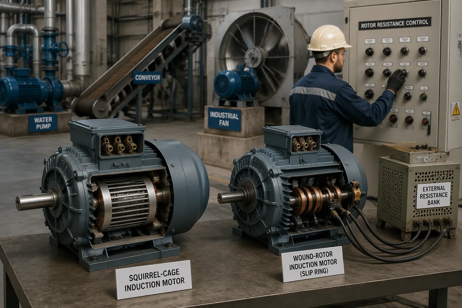
The induction motor really earns its title as the industrial workhorse. It is the most common among all ac motor types. Factories choose it for its simple, tough build, low upkeep, and low price. These machines use electromagnetic induction to create rotor current and produce torque. This design is strong, proven, and fairly simple; it also needs no magnets. Since the motor has no brushes, it makes no sparks, so it is safe in dangerous places. It can also run for long stretches without issues. The downside is that it controls speed and torque less exactly than synchronous units.
Squirrel Cage Induction Motors
The squirrel-cage induction motor is the most commonly used rotor design. Its rotor bars sit in slots and connect to end rings, forming a tough cage. This design offers fixed speed, low cost, and little upkeep. A three-phase squirrel-cage induction motor runs water pumps, fuel pumps, oil pumps, fans, conveyors, compressors, and machine tools. High-efficiency, compact, and variable-speed versions fit pumps, fans, conveyors, and process or packaging lines. Cranes, hoists, and material-handling equipment also use these motors. The table below shows the two main types of induction motor.
Motor Type | Market Position | Typical Applications |
|---|---|---|
Squirrel-cage | Most common rotor design | Pumps, fans, conveyors, general-purpose drives |
Wound-rotor | Niche roles; smaller share | Large hoists and slurry pumps needing external rotor resistance |
Wound Rotor Induction Motors
The wound rotor design adds external resistance to the rotor circuit. This feature raises starting torque and lowers inrush current. It also has adjustable speed and torque. A worker changes the external resistance to control speed, then lowers it as the motor speeds up. This makes the asynchronous motor useful for heavy loads. A wound rotor induction motor fits cranes, hoists, elevators, mills, and machines with large flywheels like punch presses and shears. Mining uses it for ore crushers, conveyor systems, and grinding mills. Cement plants use it for rotary kilns, raw mills, and clinker grinders. Steel mills use it for rolling mills and heavy-duty conveyors. Ports and marine sites use it for cranes, hoisting systems, and winches. Power plants use it for large fans and pumps under high-load startup.

A wound rotor induction motor is great for heavy jobs that need high starting torque, like cranes, hoists, elevators, mills, and machines with big flywheels such as punch presses and shears. Its adjustable rotor resistance allows controlled startup and variable speed performance.
Both designs share the same basic idea. A three-phase induction motor creates a rotating field in the stator. The rotor follows that field and produces torque. The wound rotor simply gives engineers a way to control starting behavior and speed. The squirrel cage gives them simplicity and low cost. Together, these two types of industrial motors handle most factory floor needs.
Industrial Motors and Their Uses: Single-Phase AC Motors
Single-phase ac motors handle lighter jobs in factories and businesses. They go from small fractional horsepower up to about 5 HP, and most run between 0.25 HP and 5 HP for pumps, compressors, fans, and small machines. Standard units have a continuous duty rating, so they can run all day at their rated load. Intermittent-duty versions use lighter parts and cost less, like a valve actuator that opens and closes a mechanical valve on a schedule. A plant manager who compares types of industrial motors will see that single-phase ac motors fit small equipment, while three-phase ac motors do the heavy work.
Split-Phase and Capacitor-Start Motors
A split-phase motor uses a starting winding with more resistance than the main winding. This design makes moderate starting torque, and it pulls high starting current. Efficiency is about 65%, and the motor runs at a lagging power factor. These traits fit easy-starting loads like small pumps, blowers, and bench tools.
A capacitor-start motor puts a capacitor in series with the starting winding. That capacitor makes much higher starting torque, and efficiency goes up to at least 70% and can pass 90%. The motor also runs close to unity power factor. Compressors, conveyors, and farm equipment gain from this stronger start. Both designs are among the common ac motor starting methods that engineers compare.
Motor Type | Starting Torque | Efficiency |
|---|---|---|
Split-phase | Low | About 65% |
Capacitor-start | Much higher | 70% to over 90% |
Permanent Split Capacitor and Shaded Pole Motors
A permanent split capacitor (PSC) motor keeps a capacitor in the circuit all the time. It runs quietly and handles continuous duty well. Common jobs include fan coil units, condenser fans, furnace blowers, exhaust fans, and swimming pool pumps. HVAC equipment depends on these motors for steady air movement.
A shaded pole motor uses a copper ring around part of each pole to make rotation. It costs little and gives low power, from 1/300 HP up to 1/6 HP. Efficiency stays around 10% to 35% because the shading ring causes constant losses. Small blowers, ventilation fans, and range hoods use this design. Unlike three-phase induction motors, these single phase ac motor designs trade efficiency for simplicity and low price. Along with ac induction motors and other induction motors, they complete the range of industrial motors and their uses across a facility.
Engineers weigh speed control, starting torque, and maintenance when choosing an induction motor or its synchronous rival. Synchronous units hold constant speed and correct power factor but need complex starters. Induction motors provide rugged, low-cost service across most plants.
Matching torque, speed, and duty cycle to the load matters most. Simple ac motor selection tips: select synchronous for fixed-speed duties and reactive-power correction; select induction for general-purpose work. These choices show why use an ac motor fits each job.
Variable-frequency drives strengthen the induction motor advantage. For centrifugal pumps and fans, VFDs cut energy use, because power draw falls roughly with the cube of speed reduction.
FAQ
Which AC motor type suits constant-speed industrial loads?
Because its rotor locks to the field, a synchronous motor keeps speed exact. Factories choose it for large compressors, mills, and crushers. It can also fix power factor when over-excited. But it costs more and needs a separate starting source.
Why do induction motors dominate factory floors?
Induction motors are cheap, tough, and very easy to maintain. The squirrel cage design is the most commonly used rotor design. These motors run pumps, fans, conveyors, and machine tools without brushes or sparks.
When does a wound rotor motor beat a squirrel cage design?
A wound rotor motor adds external resistance to the rotor circuit, which raises starting torque and allows speed control. It fits cranes, hoists, mills, and crushers. The squirrel cage design stays simpler and cheaper for general-purpose work.
What separates single-phase motors from three-phase motors?
Single-phase motors handle lighter loads up to about 5 HP and power small pumps, fans, and blowers. Three-phase motors give higher starting torque and better efficiency for heavy industrial jobs above 1–2 HP.
How do variable-frequency drives improve motor efficiency?
A VFD changes applied frequency and voltage to set speed and torque. It avoids high inrush current at startup. For centrifugal pumps and fans, VFDs cut energy use.


